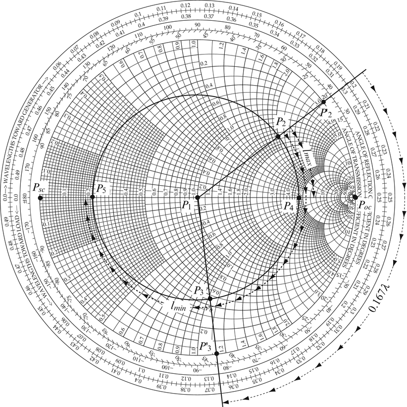

It is as if the same energy in the line had been applied to an impedance with values of resistance and reactance that create the same phase relationship. At each point, the combination results in voltage and current with a phase relationship different from either the incident or reflected waves. The incident and reflected voltage and current waves combine at every point along the line. The phase of the voltage and currents making up the reflected wave will differ from those in the incoming or incident wave depending on the value of the impedance causing the reflection. In a transmission line, when a wave of RF voltage and current encounters an impedance different from the characteristic impedance of the transmission line, Z 0, some of the energy in the wave is reflected back towards the wave’s source. R and X are the rectangular coordinates of the impedance. The vertical axis represents reactance (X): positive (inductive) above the origin and negative (capacitive) below. The horizontal axis represents resistance (R): positive to the right of the origin and negative to the left. Positive resistance which represents loss is on the positive X axis. Inductive reactance is positive (+Y axis) and capacitive reactance is negative (-Y axis). The X axis represents resistance (R) and the Y axis represents reactance (X). This graph shows the rectangular coordinates for any impedance. Graphically, these components are represented as a pair of axes at right angles, as in Figure 1.įIGURE 1. All impedances consist of resistance and reactance. The ARRL has made the QST articles available for downloading at Where Does the Smith Chart Come From?īefore discussing the chart, let’s back up a step. You can read these articles first or use them as references throughout this article. They provide as much background as you care to absorb, and deeper discussions than this article can provide.

First described by Phillip Smith in 1939, there are a number of QST articles and a detailed Wikipedia page ( en./wiki/Smith_chart) on the Smith Chart.


 0 kommentar(er)
